Writing "easy open" or "peelable" on a thermoformed meal tray specification, a yogurt cup drawing, or a bottle liner sheet without naming the test geometry, strip width, crosshead speed, and failure mode leaves the mechanical requirement undefined. On the exact same heat seal, a peel strength tester configured for an unsupported T-peel (ASTM F88 Technique A) and one configured with a 180° rigid backing plate (ASTM F88 Technique C) record peel forces that differ by 25% to 60%+ because folding a foil or polyester web through a tight hairpin radius adds plastic bending work to interfacial bond cleavage.
In our packaging experience section, the foundational note on cap opening force and usability established that screw-cap torque charts require a cap diameter, a clock (1 minute before induction heating versus 24 hours after capping), and a clear separation between machine readings and human hands. Our companion instrument guide on the bottle cap torque tester examined rotational closure metrology under ASTM D2063/D2063M-24. Once a rigid cup uses a heat-sealed flexible lid—or once a screw cap is unscrewed to reveal a hermetic induction seal liner bonded across the bottle neck finish—rotational torque ends and linear peel fracture mechanics take over.
Evaluating flexible heat seals and innerseals across machine metrology and human usability separates three physical domains:
- Peel strength tester metrology (
ASTM F88vs.ASTM F2824): How a constant-rate-of-extension (CRE) tensile analyzer measures15.0 mmor25.4 mm(1.00 in.) cut strips at200–300 mm/minacrossASTM F88/F88M-23Techniques A, B, and C (governed by Kendall’s elastic-plastic peel angle equation), and why whole-container45°pull-tab testing underASTM F2824-10(2020)is required to capture curved rim breakaway (F_peak), diametral propagation (F_avg), and trailing-rim tail-snap release. - Easy peel lidding film force windows, polymer fracture paths, and pinch-grip ergonomics: How adhesive interfacial peel, polybutylene-1 (
PB-1) cohesive split peel, and tie-layer delamination map onto the four quantitative force regimes (< 1.5–2.0 N/15 mmcold seals,2.5–6.0 N/15 mmeasy-open consumer targets,6.5–12.0 N/15 mmsemi-peelable lock-up, and> 15.0 N/15 mmfusion welds), and why keeping whole-cupF_peak <= 15–22 Nand the jerk ratioF_peak / F_avg <= 1.5–1.8prevents older-adult hand recoil and liquid spillage (ISO 17480, Marks et al., 2012, Bell et al., 2016, PMC10894767). - Induction seal liner construction and the three-variable sealing window: How
50 to 300 kHzelectromagnetic eddy currents heat a12–25 µmaluminum foil membrane to140–210 °Cin0.2–1.0 s, how one-piece direct-bond liners (Selig FoilSeal and Lift ‘n’ Peel) differ from two-piece wax-absorbent reseal liners (Enercon Industries), and how pairing a bottle cap torque tester with a peel strength tester diagnoses the coupledTorque × Power × Speedwindow.
Quick Engineering & Metrology Specifications
| Subsystem or Parameter | Governing Standard / Quantitative Specification | Physical Mechanism & Usability Boundary |
|---|---|---|
| CRE drive & crosshead speed | v_test = 200 to 300 mm/min (8.0–12.0 in./min; standard 250 or 300 mm/min) per ASTM F88/F88M-23 |
Servo ball-screw drive (±0.5% velocity accuracy). Viscoelastic sealants (EVA, PB-1, LDPE) read +8% to +18% higher force when speed doubles from 150 to 300 mm/min. |
| Load cell & ADC sampling rate | ASTM E4 Class 0.5 (±0.5% of reading), 20–250 N full scale, sampled at >= 500 to 1,000 Hz (1–2 ms interval) |
Rim breakaway spikes (F_peak) last 10–50 ms; slow 10–50 Hz display filters clip true F_peak by 15%–35% and hide spill-recoil hazards. |
Strip width normalization (b) |
ASTM F88: 25.4 mm (1.00 in.). EN 868-5 / ISO 11607-1: 15.0 mm (0.591 in.) |
Force (N/15 mm) = Force (N/25.4 mm) × 0.5906. 1.0 N/15 mm = 1.693 N/25.4 mm = 0.381 lbf/in.. Never compare raw Newtons without strip width b. |
| ASTM F88 tail-holding geometries | Tech A: Unsupported (~90° T-peel). Tech B: Supported 90° carriage. Tech C: Supported 180° backing plate |
Kendall’s peel equation G_c = (F/b)(1 − cos θ) − G_bend plus 180° hairpin plastic bending shifts apparent peel force by 25% to 60%+ across techniques. |
Whole-cup 45° peel (ASTM F2824) |
Intact round cup/tray in 45° fixture pulled by corner tab at 200–300 mm/min (ASTM F2824-10(2020)) |
Preserves curved rim breakaway (F_peak), two-arc diametral propagation (F_avg), and trailing-rim tail-snap across 75–120 mm containers. |
| Easy-peel lidding force window | Strip: 2.5 to 6.0 N/15 mm (0.95–2.28 lbf/in.). Whole cup: F_peak = 8–18 N (<= 22 N), F_avg = 5–14 N, F_peak / F_avg <= 1.5–1.8 |
Resists 30–60 kPa ASTM F1140 internal burst pressure while staying below 5th-percentile older female key-pinch strength (25–38 N). |
| Human tear-tab pinch mechanics | Lateral key pinch R² = 0.548 (p <= 0.001); hand disorders = 53% of healthy force (Marks et al., 2012) |
Coulomb slip limit F_pull,max = 2 × μ_eff × F_pinch requires unsealed tab length >= 10–15 mm so fingers engage a lateral key grip instead of fingertip nails. |
| Induction seal liner window | 50–300 kHz coil, 12–25 µm Al foil heated to 140–210 °C in 0.2–1.0 s (Enercon) |
Easy-peel clean liners: 3.5–8.0 N/15 mm (F_peak = 10–22 N). Tamper-evident weld liners: > 15.0–25.0+ N/15 mm (destructive foil/fiber transfer). |
How a peel strength tester measures flexible seals: ASTM F88 strips vs. ASTM F2824 whole cups
A peel strength tester is a constant-rate-of-extension (CRE) universal tensile testing instrument—configured as a vertical column frame or a horizontal motorized peel table—that separates a bonded laminate or heat seal at a controlled crosshead velocity while digitizing tensile reaction force across stroke displacement F(x). Unlike a dead-weight hang test that only shows pass/fail survival under static load, a CRE peel analyzer records the complete fracture profile: elastic web stretching, leading-edge breakaway initiation (F_peak), steady crack propagation across the seal land (F_avg), local thermal defects, and final detachment.
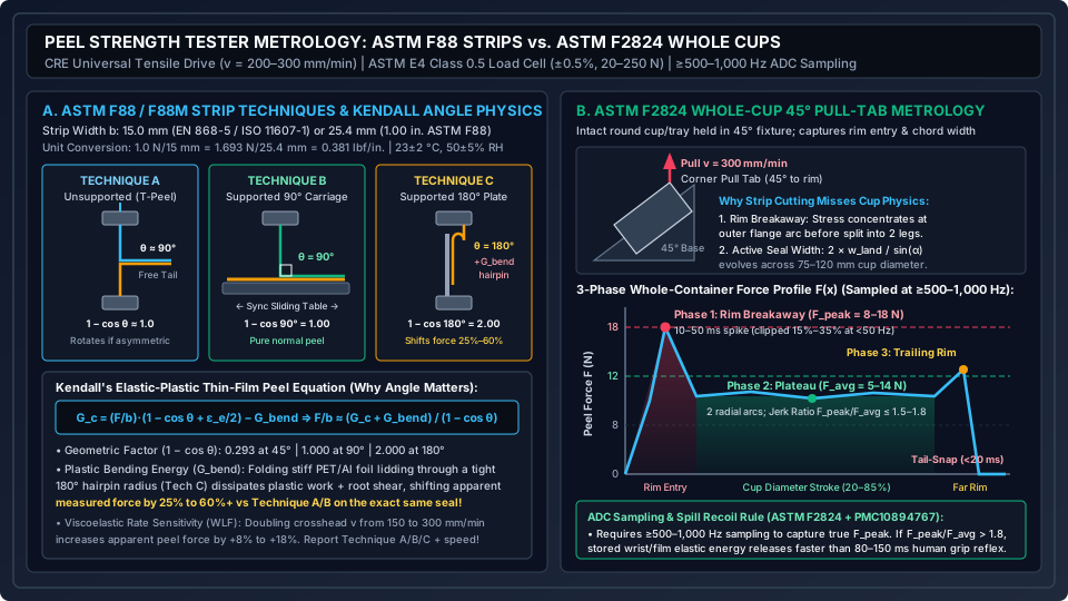
Figure 1: ASTM F88/F88M-23 strip peel geometries (Techniques A, B, and C) and Kendall’s elastic-plastic peel angle equation (left), contrasted with ASTM F2824-10(2020) whole-container 45° pull-tab kinematics and its three-phase force-displacement profile (right).
CRE tensile drive architecture, ASTM E4 load cells, and high-frequency ADC sampling (>= 500–1,000 Hz)
For a peel strength tester trace to qualify as a valid laboratory measurement under ASTM F88/F88M-23 or ASTM F2824-10(2020), three hardware subsystems must stay within calibration boundaries:
- Servo-controlled constant-rate-of-extension (
CRE) drive: A brushless servo motor and ball screw translate the moving grip at a constant velocityv_testheld within±0.5% to ±1.0%. Low-mass pneumatic or mechanical wedge grips—lined with serrated rubber or polyurethane faces—clamp the unsealed film tails at350–550 kPa(50–80 psi) to prevent slip without crushing the film at the jaw line. - Strain-gauge load cell sizing (
ASTM E4Class 0.5): The force transducer is calibrated perASTM E4to±0.5%(Class 0.5) or±0.25%of reading down to1%–2%of full scale. Because flexible lidding films and induction liners peel between1.5 Nand45 N, packaging laboratories mount20 N,50 N,100 N, or250 N(~4.5 lbfto56 lbf) load cells so the working plateau sits between10% and 80%of capacity, guarded by110% / 150%overload stops (matching theOVERsafeguards on our bottle cap torque tester guide). - High-speed analog-to-digital converter (
ADC) sampling (>= 500 to 1,000 Hz): At300 mm/min(5.0 mm/s), initial fracture of the outer heat-seal bead occurs over0.05 to 0.25 mm—lasting only10 to 50 milliseconds. Low-speed display filters (10 to 50 Hz, or20–100 msintervals) average out the initiation transient and clip true breakaway peak forceF_peakby15% to 35%. Capturing trueF_peak / F_avgrequires an internalADCsampling rate of>= 500 to 1,000 Hz(1 to 2 msinterval).
ASTM F88 / F88M strip width normalization (15.0 mm vs. 25.4 mm) and viscoelastic speed sensitivity
Under ASTM F88/F88M-23, dual-blade sample cutters excise rectangular test strips perpendicularly across the heat-sealed rim. Specimens are conditioned at 23 ± 2 °C (73.4 ± 3.6 °F) and 50 ± 5% RH for >= 24 to 40 hours (ASTM D4332), clamped at 25.4 mm (1.0 in.) initial jaw separation, and pulled at v_test = 200 to 300 mm/min (8.0 to 12.0 in./min), with 250 mm/min or 300 mm/min as standard setpoints.
European, Asian, and medical sterilization standards (EN 868-5 / ISO 11607-1) specify a 15.0 mm strip width, whereas North American ASTM F88 specifies 25.4 mm (1.00 in.). Raw Newtons must always be normalized by strip width b:
F_15mm (N / 15 mm) = F_25.4mm (N / 25.4 mm) × (15.0 / 25.4) = F_25.4mm × 0.59055
1.00 lbf / in. = 4.4482 N / 25.4 mm = 2.6269 N / 15 mm | 1.00 N / 15 mm = 0.3807 lbf / in.
| Standard & Regional Convention | Specimen Width (b) |
Tolerance | Reported Unit | Conversion to N / 15 mm |
Conversion to lbf / in. |
|---|---|---|---|---|---|
| EN 868-5 / ISO 11607-1 & Global Lidding | 15.0 mm (0.591 in.) |
±0.10 mm |
N / 15 mm |
× 1.0000 (Direct baseline) |
× 0.3807 (1 N/15 mm = 0.381 lbf/in.) |
| ASTM F88M (Metric SI Option) | 25.4 mm (or 25.0 mm) |
±0.127 mm |
N / 25.4 mm |
× 0.5906 (from 25.4 mm) |
× 0.2248 (from N / 25.4 mm) |
| ASTM F88 (North American Inch-Pound) | 1.00 in. (25.4 mm) |
±0.005 in. |
lbf / in. |
× 2.6269 (1 lbf/in. = 2.627 N/15 mm) |
× 1.0000 (1 lbf/in. = 453.6 g/in.) |
| JIS Z 0238 (Japanese Packaging Standard) | 15.0 mm |
±0.10 mm |
N / 15 mm |
1 kgf / 15 mm = 9.807 N / 15 mm |
1 kgf / 15 mm = 3.733 lbf / in. |
Crosshead speed v_test must be logged alongside width b. Heat-seal polymers (EVA, LDPE, PB-1, ionomers) follow Williams-Landel-Ferry (WLF) viscoelastic time-temperature superposition:
F(v_2) ≈ F(v_1) × (v_2 / v_1)^m (viscoelastic rate exponent m ≈ 0.10 to 0.22)
Doubling crosshead speed from 150 mm/min to 300 mm/min raises apparent peel force by +8% to +18%, while comparing a 50 mm/min check against a 300 mm/min ASTM F88 inspection introduces a 20% to 45% offset.
Why ASTM F88 Techniques A, B, and C shift peel force by 25%–60%: Kendall’s peel angle equation
When two laboratories cut 15.0 mm strips from the same tray, pull at 300 mm/min, and record 4.2 N/15 mm at Lab 1 versus 6.4 N/15 mm (+52%) at Lab 2, the root cause is tail-holding geometry. ASTM F88/F88M-23 defines Technique A (Unsupported), Technique B (Supported 90°), and Technique C (Supported 180°), which do not yield numerically identical readings.
Under Kendall’s (1975) elastic-plastic thin-film peel mechanics, peeling a web of width b at angle θ (between the pulled flexible tail and the unpeeled substrate plane) balances external crosshead work against three terms: true interfacial fracture energy G_c (J/m² or N/m), axial web elastic strain ε_e / 2, and irreversible plastic bending energy G_bend dissipated in folding the backing web (PET, PA, or Al foil) at the peel root:
G_c = (F / b) × (1 − cos θ + ε_e / 2) − G_bend
F / b ≈ (G_c + G_bend(θ)) / (1 − cos θ)
| ASTM F88 Tail-Holding Technique | Peel Angle (θ) & (1 − cos θ) |
Fixture & Clamping Geometry | Root Curvature, Mode Mixity & Bending Energy (G_bend) |
Effect on Measured Force (F / b) |
Primary Use Case & Limitation |
|---|---|---|---|---|---|
| Technique A — Unsupported (“T-Peel”) | Symmetric webs: θ ≈ 90° (1 − cos θ ≈ 1.0). Asymmetric tray-to-lid rotates (45°–135°). |
Upper and lower tensile grips only; free seal tail is unheld. | Symmetric bending on matched pouch films. On stiff 400–800 µm APET/PP tray flanges vs 45 µm film, the seal rotates toward the pull axis. |
Baseline (1.00×) for flexible pouches (PET/Al/PE). Drifts if tray stiffness varies. |
Standard for flexible pillow pouches; poor angle stability on rigid tray flanges. |
Technique B — Supported 90° Peel |
Fixed θ = 90° (1 − cos 90° = 1.000). |
Substrate held horizontally (90° to pull axis) via hand guide or synchronized sliding carriage. |
Mode I (pure normal opening) with gentle 90° curvature (low G_bend). Minimizes shear lock-up and initiation spikes. |
Reads 10% to 25% lower than asymmetric T-peel and 25% to 45% lower than 180° Tech C on foil/PET lids. |
Closest strip analogue to upright lid lifting; requires a synchronized 90° carriage for low variance. |
Technique C — Supported 180° Peel |
Fixed θ = 180° (1 − cos 180° = 2.000). |
Stiff tray strip clamped vertically against a rigid backing plate in lower grip; lid folded 180° upward. |
Folds PET / Al foil through a tight 180° hairpin radius (high G_bend) while imposing Mode II in-plane shear (raising effective G_c). |
Shifts measured force by 25% to 60%+ vs Tech A/B (highest on 20–40 µm Al foil or thick PET webs). |
Highest repeatability on flexible-to-rigid tray strips; never mix with Tech A/B specs without an offset. |
Worked calculation: how Kendall’s equation shifts a 15 mm strip reading
Consider a lidding film (12 µm PET / 15 µm Al foil / 25 µm cohesive-split sealant) sealed to a 500 µm APET tray strip with Mode I fracture toughness G_c,I = 220 J/m² (0.220 N/mm):
- Technique B (
90°sliding carriage,θ = 90°,1 − cos 90° = 1.000): Gentle90°folding dissipatesG_bend,90 ≈ 30 J/m²(0.030 N/mm), giving:F_TechB = 15.0 mm × (0.220 + 0.030 N/mm) / 1.000 = 3.75 N / 15 mm - Technique C (
180°backing plate,θ = 180°,1 − cos 180° = 2.000): Kinking the15 µmaluminum foil through a180°hairpin (R_root ≈ 0.15 mm) dissipatesG_bend,180 ≈ 410 J/m²(0.410 N/mm), while Mode II root shear raises effective toughness toG_c,eff ≈ 530 J/m²(0.530 N/mm), giving:F_TechC = 15.0 mm × (0.530 + 0.410 N/mm) / 2.000 = 15.0 mm × 0.470 N/mm = 7.05 N / 15 mm
Switching between Technique B and Technique C shifts the reading on the exact same seal from 3.75 N/15 mm to 7.05 N/15 mm (+88%, or −37% on thin non-yielding films where G_bend ≈ 0). Every ASTM F88 specification must name Technique A, B, or C.
Whole-container 45° pull-tab metrology (ASTM F2824): why strip cutting fails round cups
Cutting a flat 15.0 mm strip out of a round yogurt cup, fruit bowl, or soup tray (ASTM F88) destroys three whole-package mechanics:
- Curved outer-rim breakaway concentration: Pulling a corner tab on a round cup (
D = 75 to 120 mm) concentrates opening stress across the outer peripheral arc of the flange (radial land width w_land = 2.0 to 4.0 mm), generating a sharp initial breakaway peak (F_peak). - Splitting into two simultaneous radial seal arcs: Once the leading rim breaks, the peel front splits into two active seal arcs advancing along the left and right flanges simultaneously. Where the peel front intersects the circular rim tangent at angle
α(x), combined active seal widthb_active(x)is:b_active(x) = 2 × w_land / sin(α(x)) = 2 × w_land × R / sqrt(R² − (x − R)²) - Headspace pressure & wall deflection: Cutting the container vents internal vacuum or
MAPgas pressure and eliminates cup wall flexing.
To test the intact package, ASTM F2824-10(2020) mounts the sealed round cup into a 45° angled base fixture on the peel strength tester while the upper grip pulls the corner tab vertically at 200–300 mm/min (peeling at 45° to the flange plane), resolving three force phases:
- Phase 1 — Initial Rim Breakaway Peak (
F_peak, N,0%–15%stroke): Maximum initiation spike across the leading flange arc. Determines whether the user’s fingers slip off the tab (if F_peak > 2 × μ_eff × F_pinch). - Phase 2 — Diametral Propagation Plateau (
F_avg, N,20%–80%stroke): Mean force across the two radial flange arcs (2 × w_land / sin α). Local spikes diagnose platen temperature asymmetry or flange contamination. - Phase 3 — Trailing Rim Exit & Tail-Snap Detachment (
85%–100%stroke): The two fronts converge at the far rim (F_exit) and detach to0 Nin< 20 ms, releasing stored elastic energy in the wrist and film.
Rules of thumb:
- Use
ASTM F88(15.0 mmor25.4 mmstrips) to audit incoming film lots, platen flatness around all four sides, and polymer fracture mode. - Use
ASTM F2824(45°whole-container fixture at>= 500–1,000 Hz) to qualify corner tab geometry, chevron initiation seals, and consumerF_peak / F_avglimits.
Takeaway: A peel strength tester only produces reproducible numbers when the specification locks down strip width (15.0 mm vs. 25.4 mm), crosshead speed (200–300 mm/min), ADC sampling rate (>= 500–1,000 Hz), and test geometry (ASTM F88 Technique A, B, or C vs. ASTM F2824 45° whole-container pull).
Easy-peel lidding film force windows, fracture modes and the spill-recoil boundary
Specifying easy peel lidding film force requires matching the microscopic polymer fracture path inside the heat seal to the macroscopic biomechanics of the human hand. Under ASTM F88/F88M-23, a peel force reading in N/15 mm must always be paired with its physical failure mode (adhesive peel, cohesive split, delamination, or material break).
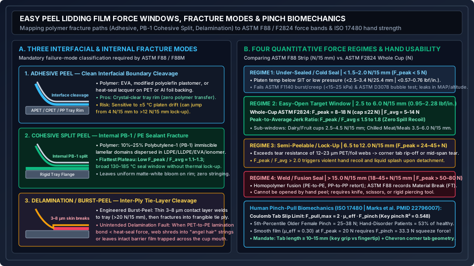
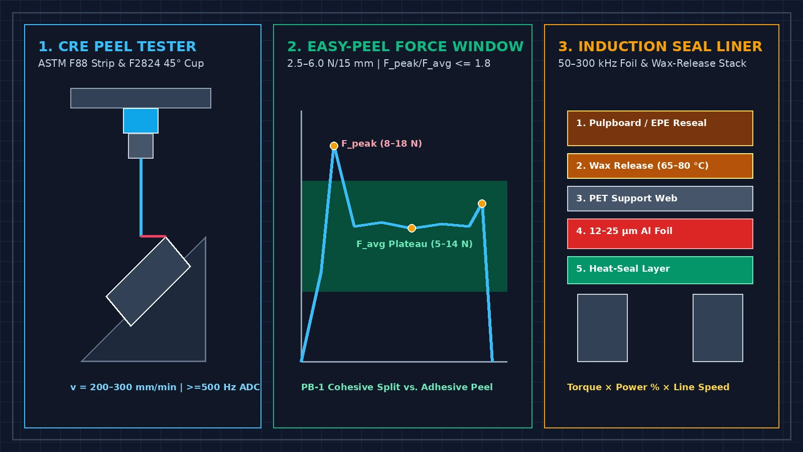
Figure 2: The three physical peel fracture mechanisms in flexible lidding laminates (left), mapped against the four quantitative peel force regimes (N/15 mm strip vs. ASTM F2824 whole-cup N) and ISO 17480 older-adult pinch-pull biomechanics (right).
Three physical peel fracture mechanisms: adhesive, PB-1 cohesive split, and tie-layer delamination
When a peel strength tester separates a flexible lidding web (35–75 µm total thickness: outer 12–23 µm BOPET, BOPA, or 15–40 µm Al foil barrier laminated to an inner 15–35 µm sealant layer) from a rigid tray flange (APET, CPET, PP, PS, PVC, or paperboard), fracture follows one of three microstructural paths:
| Peel Fracture Mechanism | Sealant Polymer Formulation & Microstructure | Microscopic Crack Propagation Path | Force Curve Signature (F_peak / F_avg) |
Visual Rim Appearance & Production Window |
|---|---|---|---|---|
| 1. Adhesive Peel (Interfacial Separation) | Copolymer sealant (EVA, polyolefin plastomer, ionomer, or heat-seal lacquer) formulated to wet polar (APET/CPET) or non-polar (PP/PE) rims. |
Cleaves directly at the two-dimensional sealant-to-tray interface (zero polymer mass transferred to the tray flange). |
Moderate to sharp initiation peak (F_peak / F_avg ≈ 1.4–2.0); sensitive to platen temperature drift. |
Crystal-clear, residue-free tray rim (preferred for clear APET salad, fruit, and fresh meat trays). Narrower thermal window (±5 °C drift can jump peel from 4 N/15 mm to > 12 N/15 mm lock-up). |
| 2. Cohesive Split Peel (Internal Sealant Fracture) | Coextruded immiscible polyolefin blend (15–35 µm thick): 10% to 25% Polybutylene-1 (PB-1) dispersed in LDPE, LLDPE, EVA, or ionomer (Surlyn). |
Extrusion draws incompatible PB-1 into microscopic lamellar platelets inside the PE matrix. Under tension, the crack runs cohesively through the middle of the sealant layer around PB-1 domains. |
Flattest plateau (F_peak / F_avg ≈ 1.1 to 1.3) with minimal initiation spike and smooth release. |
Leaves a uniform microscopic matte-white polymer bloom (~5–15 µm split skin) on both flange and lid. Broad 130 to 185 °C seal window without lock-up; zero “angel hair” stringing. |
| 3. Delamination / Burst-Peel (Inter-Ply Tie-Layer Cleavage) | Coextruded web with a thin 3 to 8 µm contact weld layer (> 20 N/15 mm bond to tray), backed by a frangible internal tie layer next to the PET/EVOH core. |
Stress fractures the 3–8 µm contact skin at the inner flange edge and delaminates along the internal tie-layer boundary across the seal land. |
High ASTM F1140 burst resistance paired with a 3.5–7.0 N/15 mm plateau when engineered as burst-peel. |
Fault (Unintended Delamination): If PET-to-PE laminating adhesive bond (< 3 N/15 mm) is weaker than the heat seal, the web shreds into “angel hair” strings or leaves barrier film across the tray mouth. |
Quantitative easy peel lidding film force windows (N/15 mm vs. whole-cup ASTM F2824 N)
Across food, dairy, medical, and consumer packaging, strip peel strength (ASTM F88 / EN 868-5 at 200–300 mm/min) and whole-container 45° pull-tab force (ASTM F2824) divide into four engineering regimes:
| Seal Force Regime | ASTM F88 Strip Force (N / 15 mm) |
ASTM F88 Strip Force (N / 25.4 mm & lbf / in.) |
ASTM F2824 Whole-Cup 45° Force (N) |
Jerk Ratio (F_peak / F_avg) |
Package Integrity (ASTM F1140) & Human Usability Outcome |
|---|---|---|---|---|---|
| Regime 1: Under-Sealed / Cold Seal (Leak Hazard) | < 1.5 to 2.0 N / 15 mm |
< 2.5 – 3.4 N / 25.4 mm (< 0.57 – 0.76 lbf/in.) |
F_peak < 5.0 N; F_avg < 3.0 N |
1.0 – 1.3 (Glossy unwet interface) |
Platen below Seal Initiation Temperature (SIT) or low pressure. Fails ASTM F1140 burst/creep (< 15–25 kPa) and ASTM D3078 bubble leak; pops open during MAP flushing or 75–80 kPa altitude transit. |
| Regime 2A: Easy-Open Target — Dairy, Fruit & Hospital Cups | 2.5 to 4.5 N / 15 mm |
4.2 – 7.6 N / 25.4 mm (0.95 – 1.71 lbf/in.) |
F_peak = 8.0 to 15.0 N; F_avg = 5.0 to 10.0 N |
<= 1.4 to 1.6 |
Optimal for single-serve yogurt, fruit cups, pudding, and hospital catering (Bell et al., 2016). Opens smoothly below 50% of 5th-percentile older female pinch strength (25–38 N) without liquid splash. |
| Regime 2B: Easy-Open Target — Chilled Meat, Cheese & Meal Trays | 3.5 to 6.0 N / 15 mm |
5.9 – 10.2 N / 25.4 mm (1.33 – 2.28 lbf/in.) |
F_peak = 11.0 to 18.0 N (cap <= 22.0 N); F_avg = 7.0 to 14.0 N |
<= 1.5 to 1.8 |
Standard commercial easy peel lidding film force target for 250–1,000 g APET/CPET/PP trays. Survives 30–60 kPa burst pressure while staying below the 22 N elderly key-pinch slip limit. |
| Regime 3: Semi-Peelable / Thermal Lock-Up Transition | 6.5 to 12.0 N / 15 mm |
11.0 – 20.3 N / 25.4 mm (2.47 – 4.57 lbf/in.) |
F_peak = 24.0 to 45.0+ N; F_avg = 15.0 to 28.0 N |
> 2.0 to 3.5+ |
Exceeds tear resistance of 12–23 µm PET/Al webs, causing corner tab rip-off, mid-span film tearing, or delamination. Demands 65%–100%+ of older-adult pinch force and triggers recoil splash. |
| Regime 4: Permanent Weld / Fusion Seal (Tool-Open Only) | > 15.0 N / 15 mm (18–45+ N / 15 mm) |
> 25.4 to 76+ N / 25.4 mm (> 5.7 – 17+ lbf/in.) |
F_peak > 50 to 90+ N (Substrate yields/tears first) |
N/A (ASTM F88 Material Break FT) |
Homopolymer fusion (PE-to-PE, PP-to-PP retort pouches, or coffee bag seams resisting 30–100+ kPa CO₂ pressure on our coffee degassing valve page). Requires knife or scissors. |
Human pinch-grip biomechanics (ISO 17480, Marks et al. 2012, Bell et al. 2016) and the jerk-ratio spill limit
Under ISO 17480:2015 (Packaging — Accessible design — Ease of opening, building on CEN/TS 15945), three biomechanical constraints explain why whole-cup breakaway peaks above 18 to 22 N or jerk ratios F_peak / F_avg > 1.8 cause consumer failures:
- Lateral key-pinch strength in older adults and hand disorders (
PMID 22796007&PMID 26686584): Marks et al. (2012, Journal of Hand Therapy, PMID 22796007) measured tear-tab Pinch Pull Force (PPF) across100patients with hand disorders (arthritis, carpal tunnel, post-traumatic injury) versus402healthy adults. Multivariable regression proved that lateral key pinch (thumb pad pressing against the radial side of the index finger middle phalanx) governs tear-tab pull force (R² = 0.548,p <= 0.001), and patients with hand disorders exerted only53%of healthy adult force. While healthy young adults generate65–105 Nof key pinch, the 5th-percentile lateral pinch strength of older females (65–80+ years) drops to25 to 38 N(and 12–22 N in arthritic hands). In hospital and community trials, Bell et al. (2016, Appetite, PMID 26686584) found that39%of older adults could not open peelable cheese portions and10%could not open water bottles. Keeping opening effort below50%–60%of Maximum Voluntary Contraction (MVC) sets theF_peak <= 15 to 22 N(target 8–18 N) ceiling. - Coulomb tab-slip friction (
F_pull,max = 2 × μ_eff × F_pinch) and the>= 10–15 mmtab length rule: Human fingers transmit axial pull forceF_pull,maxinto a flexible tab via Coulomb surface friction across the two finger contact faces:F_pull,max = 2 × μ_eff × F_pinch => Required F_pinch = F_peak / (2 × μ_eff)On smoothPET/BOPPfilm (dry skin μ_eff ≈ 0.30), pullingF_peak = 18.0 NrequiresF_pinch = 18.0 / (2 × 0.30) = 30.0 Nof normal pinch squeeze (or 50.0 N if wet/oily at μ_eff = 0.18, causing finger slip). Matte-embossed or deformable aluminum tabs (μ_eff ≈ 0.50, shown by Marks et al., 2012 to yield significantly higherPPF) cut required pinch squeeze to18.0 N. Furthermore, engaging a lateral key pinch requires an unsealed tab overhang ofL_tab >= 10 to 15 mm; tabs shorter than5–8 mmforce a distal fingertip/fingernail pinch that delivers30% to 45%less force. - Neuromuscular force-release latency (
PMC10894767) and theF_peak / F_avg <= 1.5–1.8spill boundary: Motor-control studies (PMC10894767) show that decelerating human grip and pull force requires an active central nervous system (CNS) feedback loop with a somatosensory latency oft_reflex ≈ 80 to 150 ms, which is further slowed in older adults. When a flat-rim seal breaks fromF_peak = 26.0 Ndown toF_avg = 8.0 N(F_peak / F_avg = 3.25), the unbalanced excess pull force (ΔF = 18.0 N) accelerates the hand (m_hand ≈ 0.45 kg) across thet_reflex = 0.10 sreaction delay by:Δx_recoil ≈ (1/2) × (ΔF / m_hand) × t_reflex² = 0.5 × (18.0 N / 0.45 kg) × (0.10 s)² = 0.20 m = 200 mmThat uncontrolled200 mmbackward jerk flexes the cup wall and ejects soup, fruit syrup, or yogurt whey. Replacing a flat rim chord under the tab with a60°–90°chevron (V-shaped) initiation apex focuses breakaway onto a1–2 mmpoint, keepingF_peak / F_avg <= 1.5 to 1.8.
Rules of thumb:
- If
ASTM F2824whole-cup testing recordsF_peak > 22 NorF_peak / F_avg > 1.8, contour the heat-seal die under the corner tab into a chevron initiation apex or switch to aPB-1cohesive-split sealant (F_peak / F_avg ≈ 1.1–1.3). - Always provide
>= 10 to 15 mmof unsealed, textured corner tab overhang so older adults can use a lateral thumb-index key pinch.
Takeaway: Consumer easy-open performance requires pairing a 2.5–6.0 N/15 mm strip peel force (preferably via PB-1 cohesive split) with a >= 10–15 mm textured key-pinch tab, a whole-cup breakaway peak F_peak <= 15–22 N, and a jerk ratio F_peak / F_avg <= 1.5–1.8 so the seal opens smoothly within human neuromuscular reflex limits.
Induction seal liners: one-piece vs. two-piece construction and the three-variable sealing window
When a rigid bottle or jar (HDPE, PP, PET, PVC, or treated Glass) requires a hermetic barrier beneath a screw or snap cap, packaging lines install an induction seal liner (heat-induction innerseal).
As detailed by Enercon Industries, induction sealing is a non-contact electromagnetic process executed after filling and capping:
- The liner disk sits pre-inserted inside the closure (
held behind a retention bead or temporary adhesive). - After the capper applies the closure at a controlled application torque (
clamping the liner against the bottle neck land), the bottle passes on a conveyor (15–30 mmair gap) beneath an induction sealing coil energized by a50 to 300 kHzalternating-current generator. - By Faraday’s Law of Electromagnetic Induction, the oscillating magnetic field penetrates the plastic cap without heating it and induces circulating eddy currents (
I_eddy) inside the liner’s12 to 25 µm(0.5 to 1.0 mil) aluminum foil layer. - Resistive Joule heating (
P_heat = I_eddy² × R_foil) heats the foil to140 to 210 °Cwithin a0.2 to 1.0 seconddwell time, melting the bottom15 to 50 µmheat-seal polymer layer into the bottle neck land under cap thread pressure to form a360°hermetic bond upon cooling.
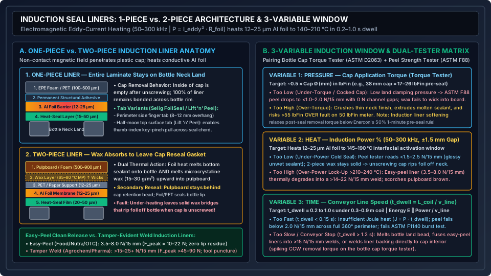
Figure 3: Multilayer anatomy of one-piece direct-bond versus two-piece wax-release induction seal liners under 50–300 kHz eddy-current heating (left), paired with the Pressure × Heat × Time three-variable operating window and dual-tester diagnostic matrix (right).
One-piece vs. two-piece induction seal liner construction
As documented by Enercon Industries and Selig Group (FoilSeal™ and Lift 'n' Peel™), every induction seal liner uses either a One-Piece or Two-Piece laminate stack:
| Structural & Functional Attribute | One-Piece Induction Seal Liner (Direct-Bond / Single Disk) |
Two-Piece Induction Seal Liner (Wax-Release with Cap Reseal Backing) |
|---|---|---|
| Multilayer cross-section (top cap side -> bottom bottle lip) | 1. Foamed PE / EPE (150–500 µm) or PET film backing (25–75 µm)2. Permanent structural laminating adhesive 3. Aluminum foil eddy-current barrier ( 12–25 µm / 0.5–1.0 mil)4. Heat-seal polymer film/lacquer ( 15–50 µm, matched to HDPE, PP, PET, or Glass) |
1. Compressible pulpboard (500–900 µm) or foamed EPE (500–1,000 µm) reseal backing2. Microcrystalline wax layer ( 15–30 g/m², melting point 65–80 °C) or clean-release polymer tie ply3. PET or paper support film (12–25 µm)4. Aluminum foil barrier ( 12–25 µm)5. Heat-seal polymer layer ( 20–50 µm) |
Thermal action during 0.2–1.0 s coil dwell |
Heat conducts downward from the Al foil to melt the bottom sealant onto the bottle land while the upper foam/PET backing stays permanently laminated to the foil. |
Heat conducts both ways from the Al foil: downward to melt the bottom sealant onto the bottle land, and upward (> 65–80 °C) to melt the microcrystalline wax, which wicks completely into the porous pulpboard. |
| What happens when the consumer unscrews the cap | The entire one-piece liner stays bonded as a single disk across the bottle neck; the inside of the unscrewed plastic cap is empty. | The thin PET / Al Foil / Sealant innerseal stays hermetically bonded to the bottle lip, while the pulpboard or EPE foam disk remains retained inside the cap as a secondary reseal gasket. |
| Pull-tab options & ergonomics | Supports (a) Perimeter side finger tabs (8–12 mm overhang) and (b) Top-surface half-moon pull tabs (Selig Lift ‘n’ Peel™ for full thumb-index key-pinch pulling). |
Opened via small perimeter overhang tab (if easy-peel) or by fingernail/tool puncture across the thin foil membrane. |
| Dominant production fault | Under-heating causes < 2.0 N/15 mm channel leaks; over-heating extrudes sealant bead. |
“Cap Pull-Off” (Incomplete Wax Release): Under-heating or low cap torque leaves unmelted wax bridges that rip the foil off the bottle neck when the cap is unscrewed. |
Easy-peel clean release vs. tamper-evident weld induction liners
On a peel strength tester (ASTM F88 15 mm strip cut across the container land), the bottom heat-seal layer is formulated for one of two bond classes:
- Easy-Peel / Clean-Peel Induction Seal Liner (
3.5 to 8.0 N / 15 mmstrip peel;F_peak = 10 to 22 Nwhole-neck pull): Used for dairy, nut butters, sauces, spices, protein powders, nutraceuticals, and OTC medicines. Separates cleanly with zero foil, fiber, or adhesive residue on the bottle lip. Surface half-moon tabs (Selig Lift ‘n’ Peel™) allow older adults and arthritic users (Marks et al., 2012) to grip a15–25 mmsemicircular flap over the center chord using a high-strength lateral key pinch (45°–90°pull) instead of picking at a narrow rim overhang. - Tamper-Evident Weld Seal Induction Liner (
> 15.0 to 25.0+ N / 15 mmstrip peel;F_peak > 45 to 90+ N): Used for agrochemicals, solvents, peroxides, and pharmaceuticals (Selig FoilSeal™). Homopolymer sealant fusion-welds into the bottle land; attempted hand peeling causes destructive foil/fiber delamination on the rim, requiring tool puncture to open.
The three-variable induction sealing window (Pressure × Heat × Time) and dual-tester diagnostics
As Enercon Industries explains, induction sealing is governed by the Three-Variable Induction Window (Pressure × Heat × Time), coupling a bottle cap torque tester (ASTM D2063) with a peel strength tester (ASTM F88):
- Variable 1 — Pressure (
Cap Application Torqueon Bottle Cap Torque Tester): Screw-cap thread torque supplies the downward clamping pressure (N/mm²) that presses molten sealant into the bottle land (and presses pulpboard against wax/foil in two-piece liners). On our opening-force note, Enercon’s starting application torque guideline for a38 mmcap is17 to 26 lbFin(with 1-minute pre-induction removal torque reading ~50%, or ~9 lbFin for an 18 lbFin application). Because induction heating absorbs wax and softens the liner stack, post-induction cap removal torque drops below the1-minutepre-induction baseline, which is why child-resistant closures (CRC) often use a post-induction re-torquing spindle. - Variable 2 — Heat (
Induction Power %at50–300 kHzand Coil Air Gap±1.5 mm): Controls Joule powerP_heat = I_eddy² × R_foilin the12–25 µmfoil. Magnetic flux decays as~1 / d², so a3–5 mmrail height drift or cocked cap shifts foil peak temperature by20–45 °C. - Variable 3 — Time (
Conveyor Line Speed v_line, Dwell Timet_dwell = L_coil / v_line = 0.2–1.0 s): Thermal energy scales asE_thermal ∝ P_coil × L_coil / v_line. Ramping line speed without tachometer-linked power scaling starves the seal of heat.
| Production Fault Signature | Bottle Cap Torque Tester (ASTM D2063) |
Peel Strength Tester (ASTM F88 15 mm Strip across 4 Quadrants) |
Root Cause in Pressure × Heat × Time Window |
Corrective Action |
|---|---|---|---|---|
1. 360° Cold Seal & Glossy Unwet Liner |
Pre-seal application torque Normal (e.g., 20 lbFin on 38 mm cap). |
< 1.5 – 2.5 N / 15 mm across all 4 quadrants; glossy unmelted polymer. |
Under-Heat or Short Dwell: Power % too low, air gap > +3 mm, or line speed too fast (t_dwell < 0.15 s). |
Raise generator power % in 3%–5% steps, lower coil gap, or sync power to conveyor speed. |
2. Single-Quadrant 0 N Channel Leak |
Normal torque or cocked / cross-threaded cap. | 3 quadrants = 5.0–7.0 N/15 mm, 1 quadrant = 0.0–1.0 N/15 mm (at neck mold seam). |
Local Pressure Loss: Neck land step/flash at parting line, worn capper chuck, or tilted cap. | Check neck land flatness (±0.08 mm), align capper chuck, and verify pre-seal torque. |
| 3. Two-Piece “Cap Pull-Off” (Foil Stays in Cap) | Low immediate removal torque (< 6–8 lbFin) OR low coil power. |
Foil-to-bottle peel < 1.5 N / 15 mm, while foil-to-pulpboard wax bond reads > 3.0–5.0 N / 15 mm. |
Incomplete Wax Absorption (< 65–80 °C): Low clamping pressure or insufficient foil heat leaves solid wax bridges. |
Set application torque inside Enercon’s cap-size band and raise power % until 100% of wax wicks into board. |
4. Easy-Peel Thermal Lock-Up (Tears Foil) |
Normal pre-seal torque; post-seal removal torque drops from liner thinning. | Easy-peel liner (spec 3.5–8.0 N/15 mm) spikes to > 14.0 – 22.0+ N / 15 mm (foil tear FT + brown scorch). |
Over-Heat or Long Dwell (> 210–240 °C): Power % too high or bottle stopped under active coil (t_dwell > 1.2 s). |
Reduce power % by 5%–10% and wire a conveyor-stop coil interlock. |
| 5. Backing Welded to Cap + Crushed Neck | Pre-seal torque Excessive (near 55 lbFin OVER limit on 50 lbFin meter). |
Extruded melt bead; erratic peel (2–18 N/15 mm) on deformed bottle land. |
Over-Torque + Over-Heat: Capper clutch crushes thin neck while overheating welds backing into cap shell. | Reduce capper clutch to 17–26 lbFin (38 mm) and lower coil power. |
Worked operating-window protocol: qualifying a 38 mm easy-peel induction liner
To qualify a 38 mm two-piece easy-peel induction liner (target: 4.0–7.5 N/15 mm under ASTM F88 Technique B 90° peel at 250 mm/min, clean wax release, and whole-neck F_peak <= 18 N) on an HDPE bottle at v_line = 24.0 m/min (0.40 m/s) under a L_coil = 0.24 m coil:
- Dwell time (
t_dwell):t_dwell = 0.24 m / 0.40 m/s = 0.60 s(centered inside 0.2–1.0 s). - Pre-induction cap torque (
Variable 1): Verify20.0 ± 1.5 lbFinapplication torque (~10.0 lbFin1-minute immediate removal torque) on a bottle cap torque tester. - Induction power sweep (
Variable 2): Test 5-bottle sets from45%to80%power at24 hours:45%–50%power:1.4–2.1 N/15 mm(cold seal) + partial wax cap pull-off.55% to 70%power (Qualified Window): Flat plateau at5.1 to 6.4 N/15 mm,100%clean wax absorption,> 70 kPaASTM F1140burst integrity, and whole-neck pullF_peak = 13.8 N(F_peak / F_avg = 1.38).75%–80%power: Jumps to14.5–19.2 N/15 mm(thermal lock-upand foil tear).
- Production setpoint: Lock generator at
62.5%power with speed-linked scaling (±4%alarm band).
Takeaway: Troubleshooting an induction seal liner requires measuring cap application/removal torque (ASTM D2063) before and after the coil to control clamping pressure, while using a peel strength tester (ASTM F88) across all four neck quadrants to keep the bond inside the 3.5–8.0 N/15 mm clean-peel window (or > 15 N/15 mm for tamper-evident welds).
What a peel strength tester does not measure
Keeping packaging metrology rigorous requires stating where the authority of a peel strength tester stops:
- A pneumatic tensile jaw is not a human thumb and index finger: A
CREtensile machine clamps a dry15.0 mmstrip or45°pull tab inside serrated jaws that cannot slip. A human user must acquire a corner tab (often < 10 mm or wet), pinch it via skin friction (F_pull,max = 2 × μ_eff × F_pinch), stabilize a flexible container, and decelerate muscle contraction within80–150 msafter rim breakaway (Marks et al., 2012; Bell et al., 2016; PMC10894767). Passing anASTM F88strip test (4.5 N/15 mm) never makes a pack"easy to open"if the tab is4 mmlong or if a flat seal rim creates a32 Nbreakaway spike on anASTM F2824whole-cup test. - Short-term tensile peel (
200–300 mm/min) is not long-term pressure creep (ASTM F1140): Pulling a seal apart in3 secondsmeasures high-rate fracture resistance. Under sustained internal gas pressure—such as the30 to 100+ kParoasted coffeeCO₂offgassing pressure analyzed in our coffee degassing valve guide or altitude transit (75–80 kPaambient)—viscoelastic polymer chains untangle slowly (seal creep), requiring ASTM F1140/F1140M static pressurization testing. - Mechanical opening force is not a sensory taste, aroma, or texture result: Just as a one-way valve’s stated job is separate from a tasting score on our packaging and food expectations note and tactile cues are separate from basic tastes on our texture and expectation page, evaluating whether a lidding film or induction liner alters product flavor or aroma requires a blind human panel following our sensory test design checklist.
| Question Being Asked | Correct Instrument or Method | Governing Standard / Reference | What Would Be a Category Error |
|---|---|---|---|
What linear force separates a 15 mm or 25.4 mm heat-seal strip? |
Constant-rate-of-extension (CRE) peel strength tester (200–300 mm/min) |
ASTM F88/F88M-23 (Techniques A, B, C) & EN 868-5 |
Comparing a Technique B (90°) reading against a Technique C (180°) reading, or omitting strip width b. |
What breakaway (F_peak) and plateau (F_avg) forces occur on an intact round cup lid? |
Peel strength tester with 45° whole-container base fixture (>= 500–1,000 Hz ADC) |
ASTM F2824-10(2020) | Cutting a 15 mm flat strip out of a round cup and assuming it predicts whole-cup rim breakaway or liquid spill. |
| Does the sealed package survive internal gas pressure, MAP flushing, or altitude creep? | Internal pressurization burst & creep tester | ASTM F1140/F1140M-13(2020)e1 | Relying on a 3-second ASTM F88 tensile pull to guarantee multi-week creep resistance under CO₂ load. |
| Did the screw cap apply uniform clamping pressure to the induction liner before the coil? | Bottle cap torque tester (CW application vs. CCW removal peaks) |
ASTM D2063/D2063M-24 & Enercon torque guidelines |
Raising induction sealer power % to fix a 0 N channel leak caused by an under-torqued or cocked screw cap. |
| Can older adults or patients with hand disorders open the pack without tools or spillage? | Human accessibility panel + pinch-pull ergonomics (tab >= 10–15 mm, F_peak <= 15–22 N, F_peak/F_avg <= 1.5–1.8) |
ISO 17480:2015, Marks et al. (2012), Bell et al. (2016) |
Calling a pack "easy open" from a machine load-cell trace without checking tab length, friction, and jerk ratio. |
| Does a new lidding sealant or induction liner alter the smell or flavor of the food inside? | Blind, three-digit coded human discrimination panel (difference before preference) | Sensory test design checklist (ISO 4120 triangle test) |
Assuming an odorless mechanical seal specification guarantees zero sensory scalping or off-note transfer. |
Takeaway: Keep linear strip peel (ASTM F88), whole-cup 45° pull-tab mechanics (ASTM F2824), internal creep pressurization (ASTM F1140), rotational cap torque (ASTM D2063), human pinch-pull accessibility (ISO 17480), and blind sensory evaluation in separate columns of the specification.
Method and sources
The strip peel test geometries (Technique A unsupported, Technique B supported 90°, and Technique C supported 180°), standard specimen widths (25.4 mm / 1.0 in. and 15.0 mm), crosshead speed window (200 to 300 mm/min), and mandatory failure-mode classifications summarize the public scope and significance of ASTM F88/F88M-23. Whole-container 45° pull-tab testing for round cups and bowls (capturing F_peak breakaway and F_avg propagation) is drawn from the public scope of ASTM F2824-10(2020), and internal burst/creep pressurization boundaries come from ASTM F1140/F1140M-13(2020)e1, all accessed on 26 October 2026.
Human tear-tab pinch pull force (PPF) regressions (lateral key pinch R² = 0.548, p <= 0.001), the 53% force ratio in patients with hand disorders (n = 100 patients vs. 402 healthy adults), and the mechanical advantage of longer deformable aluminum tear tabs over short plastic tabs are cited from Marks et al. (2012, Journal of Hand Therapy, PMID 22796007). Older-adult hospital and retail packaging openability failure rates (39% failure on peelable cheese portions, 10% on water bottles) come from Bell et al. (2016, Appetite, PMID 26686584), and age-related delays in grip-force release during force transitions come from PMC10894767.
Electromagnetic induction eddy-current heating principles, one-piece versus two-piece wax-absorbent liner mechanics, the three-variable sealing window (Pressure × Heat × Time), and pre- versus post-induction torque relaxation are synthesized from Enercon Industries’ How Induction Sealing Works and Understanding Application & Removal Torque. Commercial one-piece, two-piece, clean-peel, weld, and half-moon surface-tabbed liner architectures are referenced from Selig Group’s FoilSeal™ and Lift ‘n’ Peel™ technical documentation.