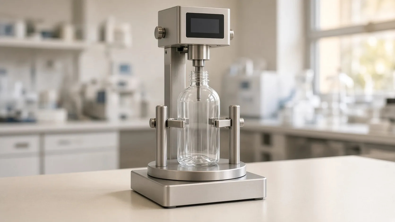
A removal number written down without the tighten number is the wrong record: the standard that defines the test only measures removal torque when the application torque is already known.
A bottle cap torque tester records application torque and removal torque as two directions, not one dial reading. ASTM D2063/D2063M-24, on the ASTM store page fetched 20 October 2026, is a quantitative method for removal torque of continuous-thread closures on containers with matching finishes. Section 5.2 limits that evaluation to controlled conditions where the application torque is known and the applied downward force on the closure is zero. The instrument side of the same job, in the Mark-10 Series TT01 user’s guide, is a tester built to measure bottle-cap application and removal torque, with clockwise and counter-clockwise peaks stored separately.
The size chart and the one-minute versus 24-hour clocks already sit on the opening-force note. This page is the tester: which peak you saved, whether the bottle was centered, and when the display is no longer a valid reading.
Quick specs
| Input or item | Typical value or source | Why it matters |
|---|---|---|
| What D2063 measures | Removal torque of continuous-thread closures, over stated conditions and time (ASTM store page, section 1.1) | The loosen reading is the result; the tighten reading is an input |
| Controlled condition | Application torque known, downward force on the closure equal to zero (section 5.2) | A push on the cap is outside that condition |
| Equipment named in section 5.3 | Non-automated spring torque meter (dial or digital) or a torque wrench | The range is limited to the instrument (section 1.1) |
| TT01 job | Measures bottle-cap application and removal torque (Mark-10 user’s guide) | One instrument, two directions |
| TT01 accuracy | ±0.3% of full scale | A 50 lbFin model is not precise to a hundredth unless the resolution says so |
| MTT01-50 capacity used below | 50 lbFin, the full-scale point in the guide’s calibration example | Sets the OVER threshold arithmetic |
| Overload | Display shows OVER at 110% and above; torque above 150% of capacity can damage the sensor | A hard twist is an instrument fault, not a cap result |
| Units on the TT01 | ozFin, lbFin, kgFcm, Nm, Ncm | ASTM says SI and inch-pound stay in separate results |
Application torque and removal torque are different operations
Application torque is the value you tighten to. Removal torque is the maximum torque later required to loosen the closure. ASTM’s public scope measures the second of those, and only as torque retention when the first is known. Section 5.3 names the tool: a non-automated spring torque meter, dial or digital, or a torque wrench. The values that can be measured stop at that equipment.
The TT01 guide is one such digital meter. It says the tester measures bottle-cap application and removal torque. On the home screen, peak clockwise and peak counter-clockwise are separate readings. Real-time mode shows the live load. Peak Clockwise (PCW) holds the maximum clockwise reading. Peak Counter-clockwise (PCCW) holds the maximum the other way. In the default numeric output, clockwise values are positive and counter-clockwise values are negative. An invert-polarity setting swaps that sign. A note that drops the sign has thrown away the direction.
The guide does not say that every cap tightens clockwise. A right-hand closure often does. The record still has to say which peak was the tighten stroke and which peak was the loosen stroke, because the instrument will store both.
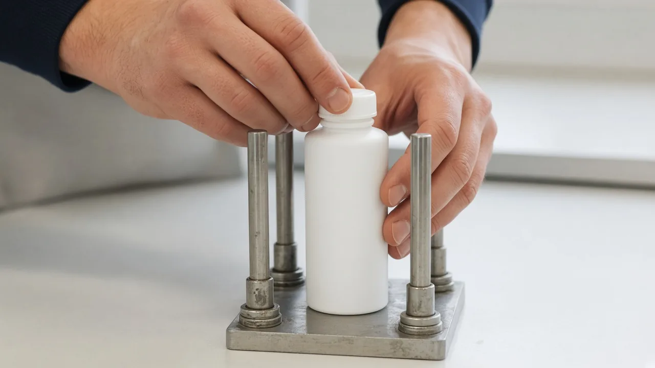
The photograph is an example of a hand on the cap and a hand on the bottle. If the bottle turns with the cap, the sensor is not seeing closure torque alone. The guide’s setup is the other way around: the sample is gripped in the posts or jaws, and the torque is applied to the cap.
| Reading | What it is | Dominant failure mode | Prevention |
|---|---|---|---|
| Application torque | Tighten target, known before the removal test (ASTM 5.2) | Writing the tighten peak into the removal column | Store the two directions separately and label which one was the tighten stroke |
| Removal torque | Maximum torque to loosen, the quantity section 1.1 measures | Taking the tamper-band peak as the thread torque | Use the second-peak function when the closure has a breakaway band |
| Downward force | Must be zero for the controlled condition in section 5.2 | Pushing down on the cap while turning | Turn without a downward load |
| Sign of the output | Clockwise positive unless polarity is inverted (TT01 guide) | Dropping the minus and mixing the two peaks | Keep the sign, or write the direction in words |
Takeaway: Label the tighten peak and the loosen peak before you compute anything from them.
A second peak is not the first peak
The TT01 guide has a first/second peak function for closures with a tamper-evident breakaway band, where two peaks can occur in one twist. Threshold 1 is a percent of full scale that ignores small peaks while the sample is loaded. Threshold 2 is a percent of full scale beyond the first peak.
The guide’s own arithmetic: for a 50 lbFin capacity tester, if the first peak is 20 lbFin and Threshold 2 is 15%, the threshold is 27.5 lbFin.
threshold (lbFin) = first peak + (Threshold 2 as a fraction × full scale)
Worked example, using those published inputs: 20 + (0.15 × 50) = 20 + 7.5 = 27.5 lbFin. The next peak has to clear 27.5 lbFin before the instrument treats it as the second peak. Recording 20 lbFin as the removal torque, on a banded cap, saves the band break and misses the thread.
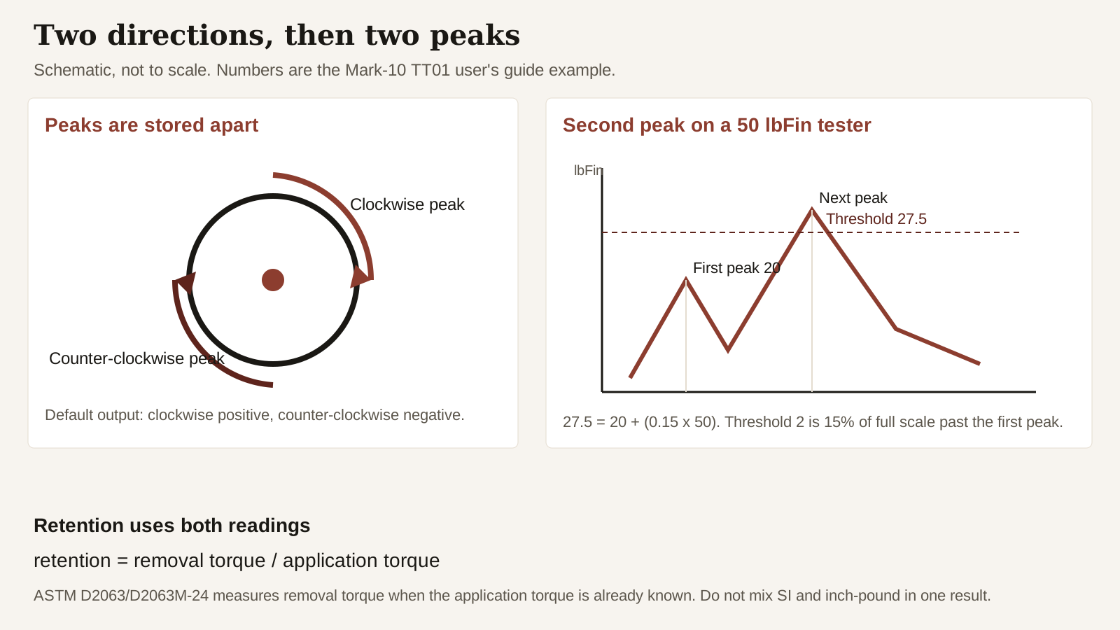
Retention, once the two labeled readings exist, is a ratio:
retention = removal torque / application torque
The opening-force note already walks through a published pair, 18 inch-pounds applied and about 9 inch-pounds removed at one minute, which is 9 / 18 = 0.50. That ratio belongs to that page’s clock and cap. It is not a pass mark for every bottle, and it is not a result this tester page measured.
Rules of thumb. If the first peak is below 27.5 lbFin on that 50 lbFin example and a band is present, do not file it as the thread removal torque, because the guide’s 15% threshold has not been cleared. If the displayed load on an MTT01-50 is above 55 lbFin, stop: 110% of 50 lbFin is 55, and the guide says the display shows OVER at 110% and above.
Takeaway: On a banded cap, decide which peak is the band and which peak is the thread before you call either one removal torque.
Center the cap, and stay inside the scale
The TT01 guide tells the operator to put the sample between the posts or jaws and tighten with the knob. Grip firmly. Excessive tightening on a thin-walled closure can deform the sample and change the result. The center of the cap should sit on the axis of the loading table. Side loading or off-center loading can produce an erroneous reading and can damage the instrument.
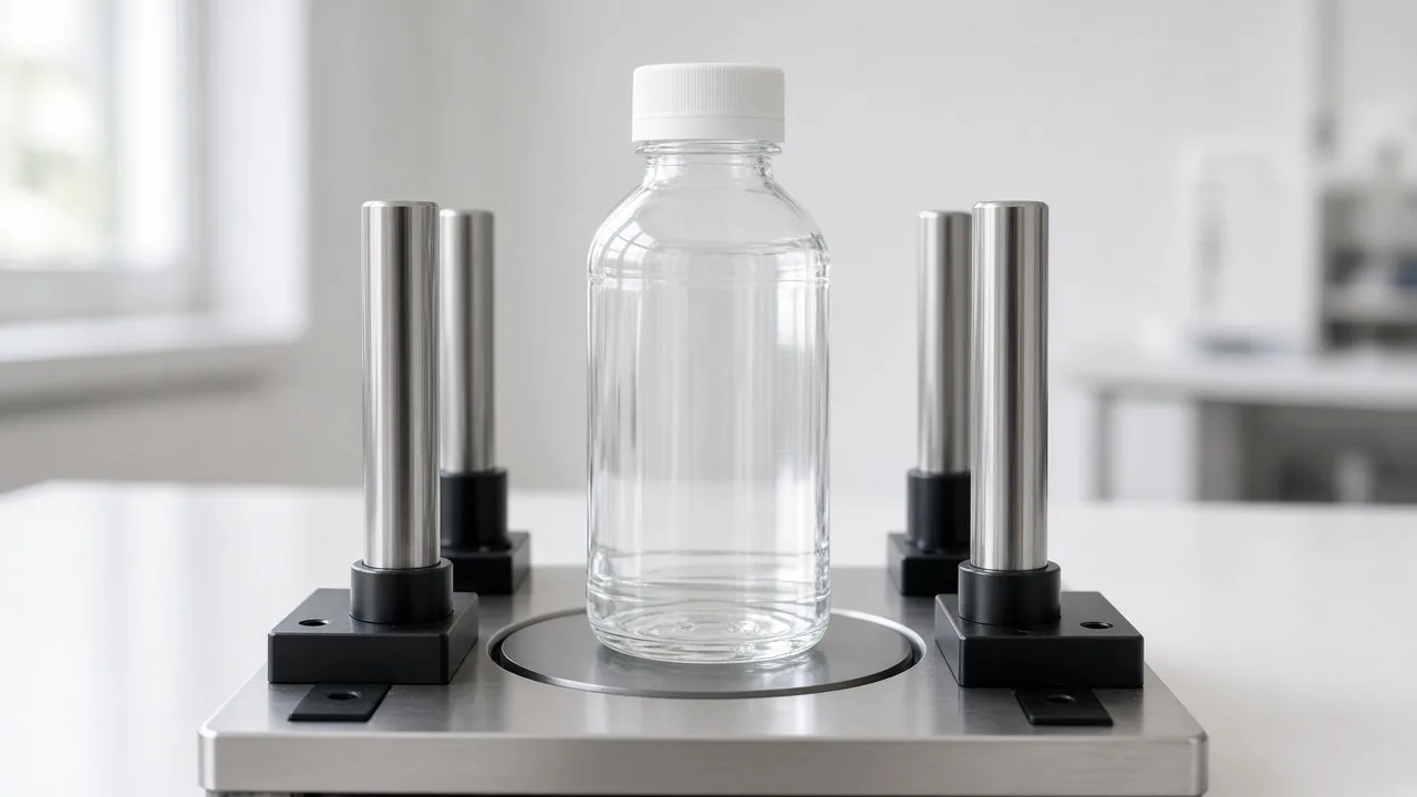
The posts in the photograph are still open. Centering is the first check; a finished grip is the next. A gap is not a measurement setup.
Capacity is part of the same check. The guide says to note the tester’s capacity before use and not to exceed it. Producing a torque greater than 150% of capacity can damage the internal sensor. The display shows OVER at 110% of full scale and above. For the MTT01-50, the calibration section treats 50 lbFin as full scale and lists calibration points at 10, 20, 30, 40 and 50 lbFin in each direction, five increments, which is the guide’s recommendation for holding the ±0.3% of full scale accuracy. The overload lines that follow from those statements:
OVER starts at 1.10 × 50 = 55 lbFin
sensor-damage torque starts above 1.50 × 50 = 75 lbFin
Those two lines are arithmetic on the guide’s 50 lbFin full scale and its 110% and 150% statements. They are not a cap specification.
The same section shows where 50 lbFin comes from in calibration. The cable radius plus the groove radius is 3.333 in (84.66 mm). Torque in lbFin equals the hung weight in pounds times that arm in inches. The guide’s example is a 15 lb weight: 15 × 3.333 = 49.995, which it treats as 50 lbFin. A different arm length is a different torque, so a shop-made weight hanger is not that calibration.
ASTM section 1.2 is the unit rule that sits on top of the meter’s five units. Inch-pound and SI are each standard on their own. They are not exact equivalents. Combining them in one reported result can put the result out of conformance. Note 1 says the SI system is the recommended system. A sheet that converts 50 lbFin into N·m and then mixes that converted figure with an inch-pound chart has left section 1.2. Keep one system for the whole note. The opening-force note stays in inch-pounds for that reason.
Rules of thumb. If the cap center is off the table center, the reading is not yet closure torque: Mark-10 says off-center loading can be wrong and can damage the sensor. If a thin-wall bottle is crushed by the posts, the torque is of a distorted closure, not of the package you meant to test.
The cost of a bad setup is a repeated sample set. ASTM’s public text does not print a specimen count on the store page, so this page does not invent one. What it does say is that the removal result is only meaningful inside the condition in section 5.2, on equipment that can actually display it. An OVER reading, a crushed bottle, or a band peak filed as thread torque all fail that condition, and the lot has to be read again. None of that is a measure of whether a person can open the pack. For a difference people can taste or feel, the next page is the sensory test checklist, not a torque unit.
Takeaway: Center the cap, stay under 55 lbFin on an MTT01-50, and do not convert units in the middle of the note.
When this does not apply
D2063/D2063M-24, as far as the public store page goes, is removal torque of continuous-thread closures with matching finishes. It does not, on that page, become a pouch-seal test, a peel-tab test, or a hand-strength study. Section 5.3’s tools are a manual spring meter or a torque wrench. An automated closer with a stated downward force is outside section 5.2.
The TT01 figures above are that model’s user’s guide: accuracy, peaks, overload, and the 50 lbFin calibration example. They are not the capacity of every cap torque tester, and the four model numbers in the guide (MTT01-12, MTT01-25, MTT01-50, MTT01-100) are not interchangeable full-scale values. The 55 and 75 lbFin lines are for the 50 lbFin scale only.
The 0.50 retention example is the other page’s Enercon pair, used here only as arithmetic. It is not a removal-torque chart for a closure diameter. This site does not run the test and does not set a consumer opening limit.
Takeaway: Use the method on a continuous-thread closure, with a known application torque, on a scale that can display the removal peak.
Method and sources
The ASTM sentences are from the store page for D2063/D2063M-24 as fetched on 20 October 2026: scope sections 1.1 and 1.2, Note 1, and significance sections 5.1 to 5.3. The full method is sold by ASTM and is not reproduced here. Instrument behavior, the 20 lbFin / 15% / 27.5 lbFin example, the ±0.3% accuracy, the 110% and 150% overload statements, the 3.333 in arm, and the MTT01-50 points at 10 through 50 lbFin are from the Mark-10 Series TT01 user’s guide PDF fetched the same day. The 9/18 ratio points at the opening-force note rather than repeating that page’s cap-size table. Photographs are unlabeled examples of a fixture and a hand turn, not a named lab and not a test result.